|
3. Composition of the Time Difference Comparison Compensator (TDCC)
in the case (1) used in the Two-Degrees-of-Freedom Control
The block diagram of TDCC is shown in Fig.1 in the usage of
the two-degrees-of-freedom control.
Besides the usual comparison between a desired value |

|

|
|
|
Fig.1 Block diagram of TDCC
for the two-degrees-of-freedom control The delay element |
Fig.2 Equivalent block diagram of Fig.1
The transfer function of the desired- value's filter is given as |
|
4. Two-Degrees-of-Freedom Control composed with
Time Difference Comparison Compensator (TDCC) and PID controller
We introduce the feedback control system constructed as shown in Fig.3.
In Fig.3, |

|
| Fig.3 Two-degrees-of-freedom control system with the use of TDCC |
|
PID controller
Thus, the set of the tuning parameters of this Two-Degrees-of-Freedom Control is
Design method is as follows.
As mentioned above, big feature in this two-degrees-of-freedom control is
that there are three big advantages, which are not difficult only by PID controller, as described in the followings.
|
or the influence of a disturbance  to the controlled output to the controlled output
comes to be minimized under some appointed gain margin. |
value becomes into an optimal condition. |
||||
gain coefficient |
the direct comparison or Phase-lead time |
time of TDC compensator |
|||
|
5. Application Examples
As an instance, we treat a servo system |

|
|
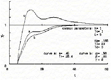
Fig.4 Indicial responses in the case of Curve a, curves from b to e and curve f indicate the responses by the TDCC, by the several usual methods and when the TDCC is removed, respectively. |

|
|
Fig.5 Indicial responses in the case of Curves a, b and c indicate the responses by TDCC, by the best usual method and when the TDCC is removed, respectively. |
Comparison Compensator |
|||||
|
6.
Difficullty in Application of This Two-Degrees-of-Freedom Control to a Real System
When this two-degrees-of-freedom control is applied to the real servo-system in which the control object possesses mechanism of nonlinear friction with hysteresis, it has to be taken into account that there may be difficulty in design of this two-degrees-of-freedom control likely as in the ordinary control method. 7. References and patents about TDCC in the usage of two-degrees-of-freedom control
(1) Nobuo YAMAMOTO and Hitoshi OOUCHI: Two-Degrees-of-Freedom PID Control with the Use of Desired-Value's Filter Composed of Time-Difference Comparison, IEEJ Trans. D, Vol.123, No.3, pp.247-256 (2003) (in Japanese).
|
